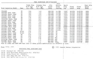
Chevrolet first printed “Form 1514C, Fuel Injection Specifications” in July of 1965 to document tuning info for all the FI model series from 1957 through 1965. Fuel injection mechanics have been using this one page data sheet as their primary reference source for calibration settings ever since. At first glance it seems to have all the data needed to calibrate a Rochester fuel injection system installed on a stock Corvette engine. Well, except that a lot of the stop settings listed are nonsense.
Frankly, I have no idea how most of the recommended nozzle pressures listed on that sheet were determined. I’ve never seen a GM or Rochester chart showing the nozzle orifice sizes originally installed in the 19 different FI model series. I think having such a chart is essential to understanding why the author of Form 1514C thought the calibration pressures he listed were appropriate. I’ve found through my own hot testing that some of those listed set pressures just don’t work well.
Engine displacement, compression ratio, camshaft grind, and engine load pretty much determine the nozzle discharge volume needed at any particular rpm. Then, once you pick a nozzle orifice size, it’s a relatively straight-forward calculation to determine how much fuel pressure at the nozzle inlet is optimum for each enrichment lever stop setting. So…. why did the author of Form 1514C list so many different stop settings for different unit series that were installed on nearly identical 283 engines with nearly identical nozzle sizes? It doesn’t make any sense that a ’57 7014520 series FI with Q nozzles should have stop settings about 50% higher than a ’58 7014900R unit with Q nozzles when they are both mounted on 283 engines with the 097 Duntov cam.
My biggest objection to GM’s “nozzle pressure” calibration method is that it doesn’t produce consistent air / fuel ratios from unit to unit. I believe this is the result of two quality control (or engineering design) issues that Rochester never addressed. Most importantly, I suspect the fuel meter gear pumps produced by Rochester NEVER had identical performance curves, even when they were new. Now that they have about fifty years of wear on them, I think the output of each pump varies considerably. Also, consider this: the nozzle orifice discs were manufactured from very thin stainless steel. These discs “take a set” when first subjected to high gasoline pressure on one side. They inelasticly deform, in other words, and that uniquely affects the shape, volume, and pressure of the fuel spray coming from each nozzle.
I’ve found that the only way to ensure correct air / fuel ratios is to calibrate every unit on a hot engine using a chassis dynamometer. I’ve been doing this with each unit I have restored since 2008. After I have the unit running well enough to pass all my road tests, I rent a local chassis dyno to perform instrumented testing. The dynamometer computer display allows me to watch the air / fuel ratio in real time as I fully accelerate and also as I cruise with a road resistance load. I then adjust the stops until I can generate a computer print-out proving proper calibration. A side benefit of this calibration method is that I can usually compensate for a slightly worn gear pump and even some non-stock nozzle sizes.
I’ll never again trust GM’s “nozzle pressure” method to determine calibration stop settings. It’s just not accurate enough to satisfy me.